Cartesian Waypoints with Tolerance in TrajOpt
/When translating a robot trajectory from a motion plan in a ROS system to an actual executed motion, there is an inherent loss of precision. In general, trajectories are sent to a controller that adheres to the exact position and timing constraints to the best of its ability, but compromises must be made to execute the trajectory. Additionally, robots cannot achieve infinite precision in positional accuracy because the kinematics of the system cannot be known with infinite precision. We have participated in work to maximize position and velocity accuracy, but not every process requires this level of precision. The process planning component should match the level of precision required by the application, but, traditionally, motion planners work assuming infinite precision. That is why we have now introduced tolerance into our motion planning pipeline when using Cartesian waypoints in TrajOpt.
TrajOpt is an optimization-based motion planner that uses a seed trajectory along with costs and constraints to refine towards a better trajectory. This process typically involves avoiding collisions and smoothing the motion. Previously, whenever we specified a Cartesian waypoint, the tool frame needed to adhere to the desired waypoint exactly. The total error across all six degrees of freedom (6DOF) could deviate by 1e-4 meters/radians, or it would be considered a constraint violation. In applications where we allowed free rotation or motion about an axis, the coefficient associated with that constraint could be set to zero, but users were not able to set bounds on the motion. For example, a common ROS-I application would allow free rotation about the Z-axis, so we would set the last coefficient in our waypoint coefficient vector to zero. An example of this process can be seen in the Scan N Plan Workshop.
Both the extremely high precision requirements and all-or-nothing approach to 6DOF Cartesian freedom of motion do not fit most applications. Additionally, these tight constraints can often cause unnecessary motion planning failures when a small freedom of motion would enable success. With the new tolerance parameters available in TrajOpt, we can more closely match the requirements of the system while reducing the number of motion planning failures. Now available in the trajopt_default_plan_profile are various settings to tailor the various waypoint requirements to the system’s needs.
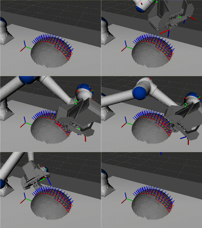
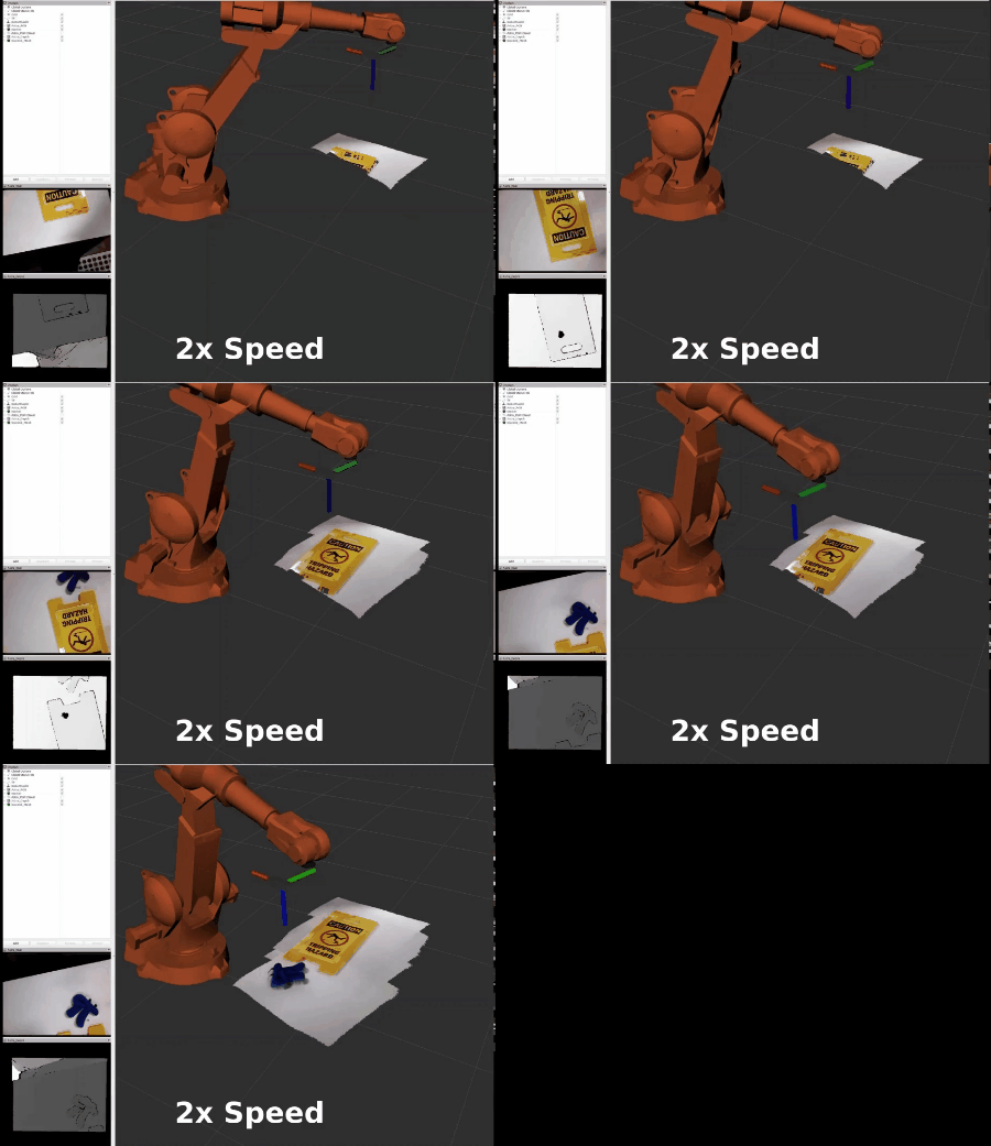
Below are two example gifs. The first shows a failed plan when no tolerance was allowed (except for free rotation about the z-axis), and the second example illustrates a successful plan when tolerance was enabled: 15 mm in X and Y, 1.5 mm in Z, and 0.01 radians in rotation around X and Y (again, free rotation about Z was allowed). Visually, these two motions look almost identical, and infinite precision would not be required for this buffing process. Using tolerance in this application will enable the robot systems to align with the process requirements and improve overall success at incorporating robotics into various processes.
failed plan when no tolerance was allowed (except for free rotation about the z-axis)
successful plan when tolerance was enabled: 15 mm in X and Y, 1.5 mm in Z, and 0.01 radians in rotation around X and Y (again, free rotation about Z was allowed)


