Mainstreaming Robotic Based Additive Manufacturing
Robotic additive manufacturing, sometimes called robot 3D printing, is evolving from research to applied technology with maturation of methodologies (gantry systems and robot arms) and source materials (metal powder, wire, polymer and concrete).
A conventional gantry system that layers material via a single x-y plane tool path is an established 3D printing solution for certain repeatable applications, while robotic arms can offer more complexity when layering material in multiple planes. However, to date traditional approaches for planning trajectories for 3D printing are not optimized for taking advantage of high degree of freedom (DOF) systems that include industrial manipulators.
Leveraging the advances in planning for high (DOF) robotic arm equipped solutions for complex additive manufacturing (AM) entails processes for planning and execution for both hardware and the work environment. The steps of a process are dependent upon often multiple proprietary software tools, machine vision tools, and drivers for motion planning end effectors, printer heads and media used in each 3D printing process.
ROS Additive Manufacturing
Over the years the ROS-I open source project and within the ROS-Industrial Consortium the creation of frameworks that enable new application development have become a standard approach to enable rapid extensibility from an initial developed application. After numerous conversations with end-users, other technical contributors, it seemed that there was an interest in looking at some of the capabilities within the ROS and ROS-I ecosystem to create a framework that seeks to take advantage of high Degree of Freedom systems and optimization based motion planning to bring a one stop shop in additive manufacturing planning and application.
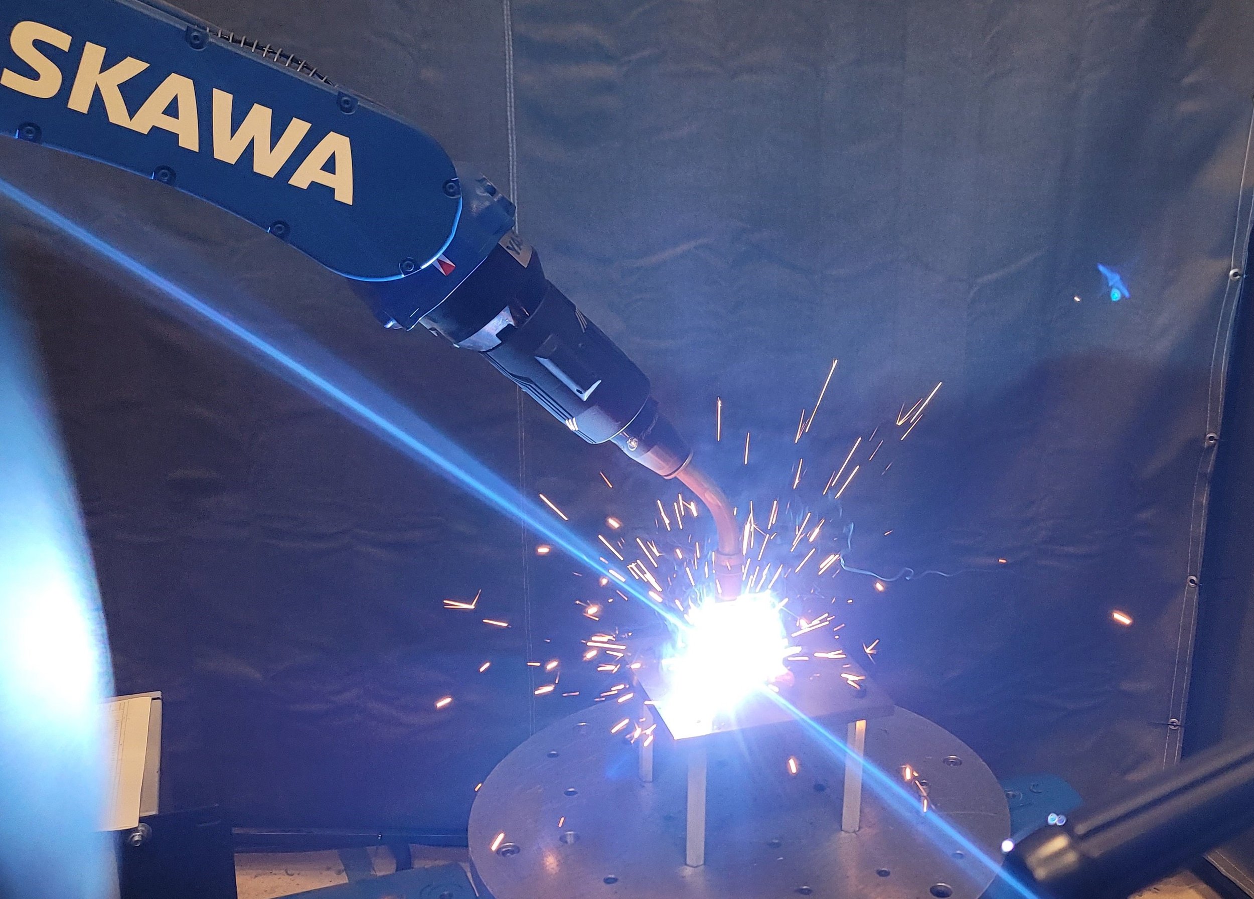
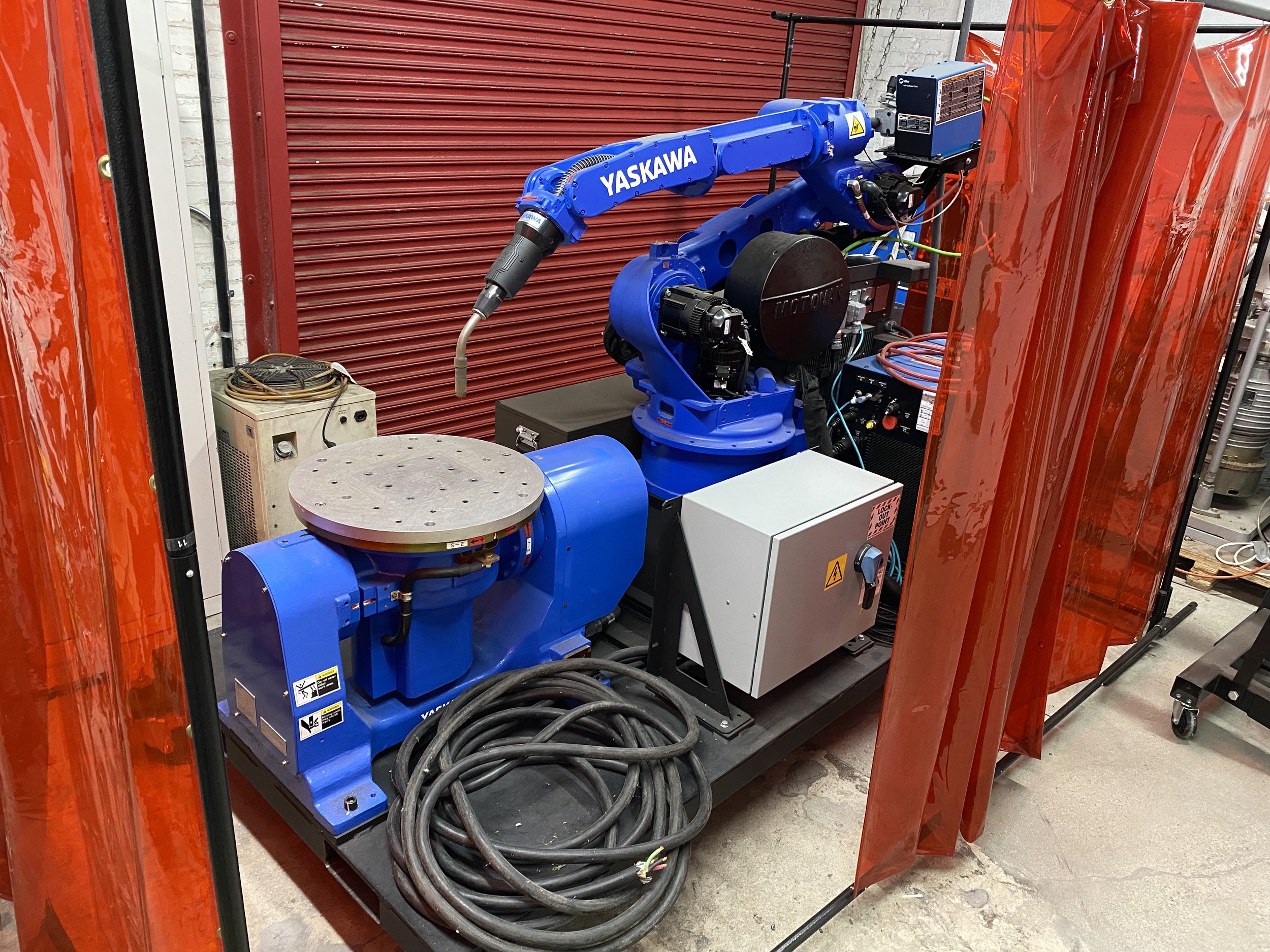
ROS Additive Manufacturing (RAM) aims to leverage the flexibility of additive manufacturing with industrial robotic applications. While looking for an open-source ROS package to slice meshes into configurable trajectories for additive manufacturing using a Yaskawa Motoman welding robot, we have been aware of the ROS Additive Manufacturing package developed by the Institute Maupertuis in Bruz, France, and so this was used as a starting point.
The RAM package was originally built in ROS Melodic, so it was rebuilt in ROS Noetic from source. Building the application from source in Noetic was mostly straightforward. We followed the the installation instructions detailed in the Maupertuis Institute's GitLab repository. The terminal commands using pip were replaced using pip3 and all terminal commands specifying ROS Melodic were replaced with ROS Noetic. When attempting to build the package in ROS, there were clashes between Sphinx 1.7.4 and the latest version of Jinja2 (version 3.1.2 as of June 2022). An older version of Jinja2 (version 2.10.1) was installed to successfully build the package and for the software to launch.
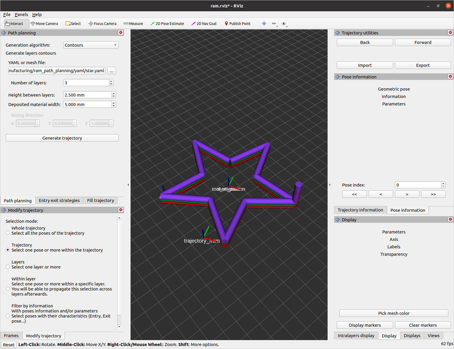
The RAM software features an RViz GUI interface that allows the user to select various trajectory generation algorithms to create a trajectory from a given mesh or YAML file. Printing parameters such as blend radius, print speed, laser power, and material feed rate can be modified for each individual layer of the print. The parameters of the entrance and exit trajectories can also be modified to have a different print speed, print angle, print length, and approach type. The output format of the exported trajectory is a ROS bag file. For our experiment, we used a Yaskawa Motoman welding robot and we needed to post-process the results to correctly interface with the robot.
Going from Plans to Robot Motion
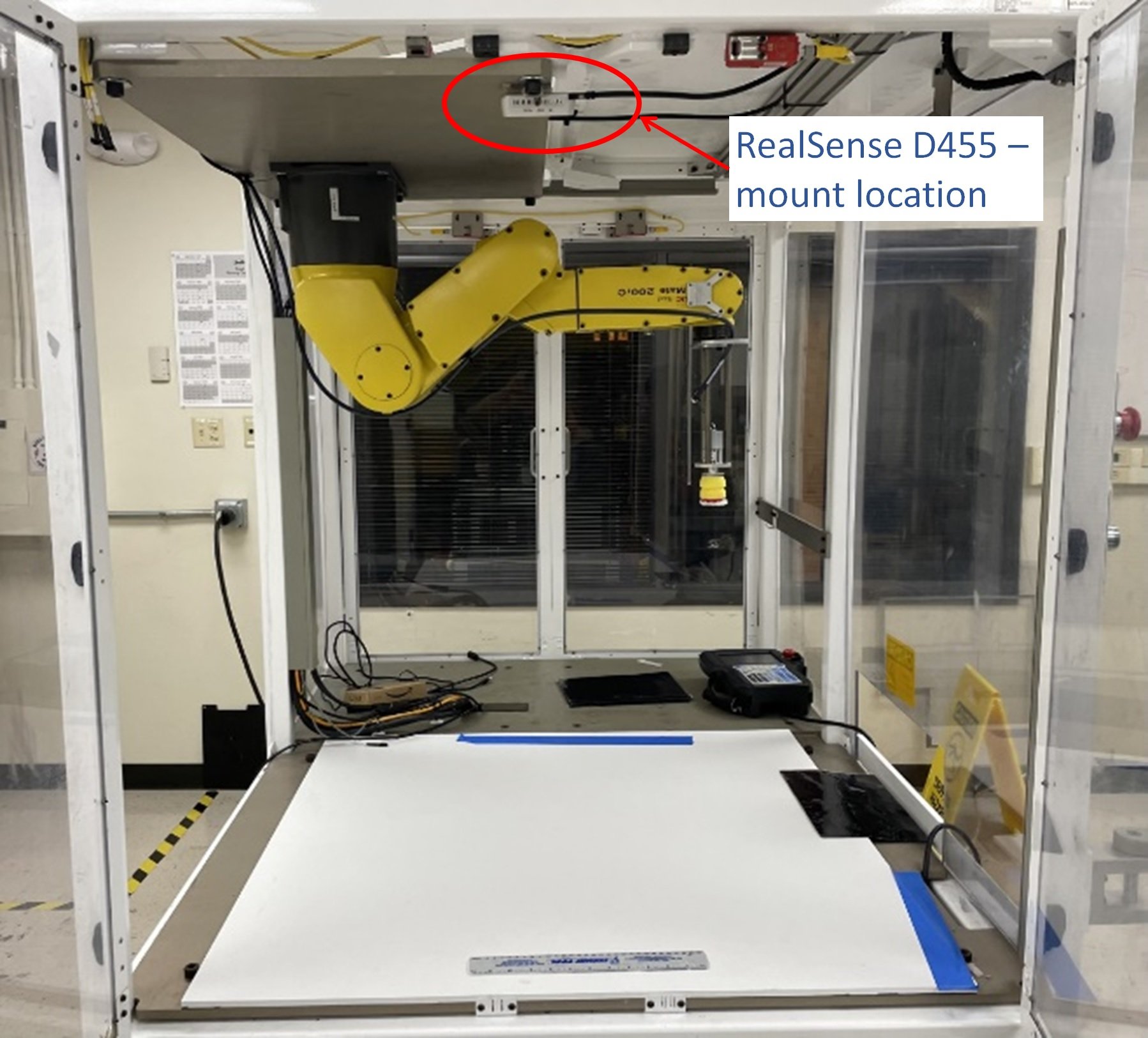
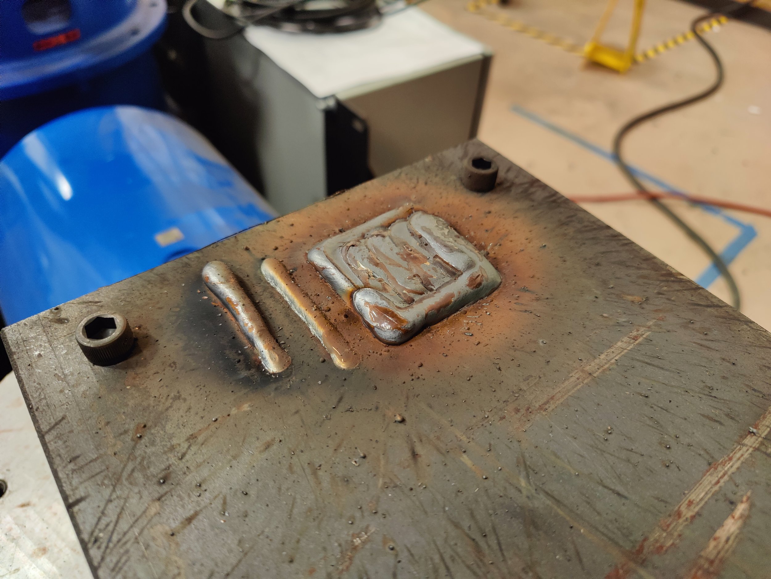
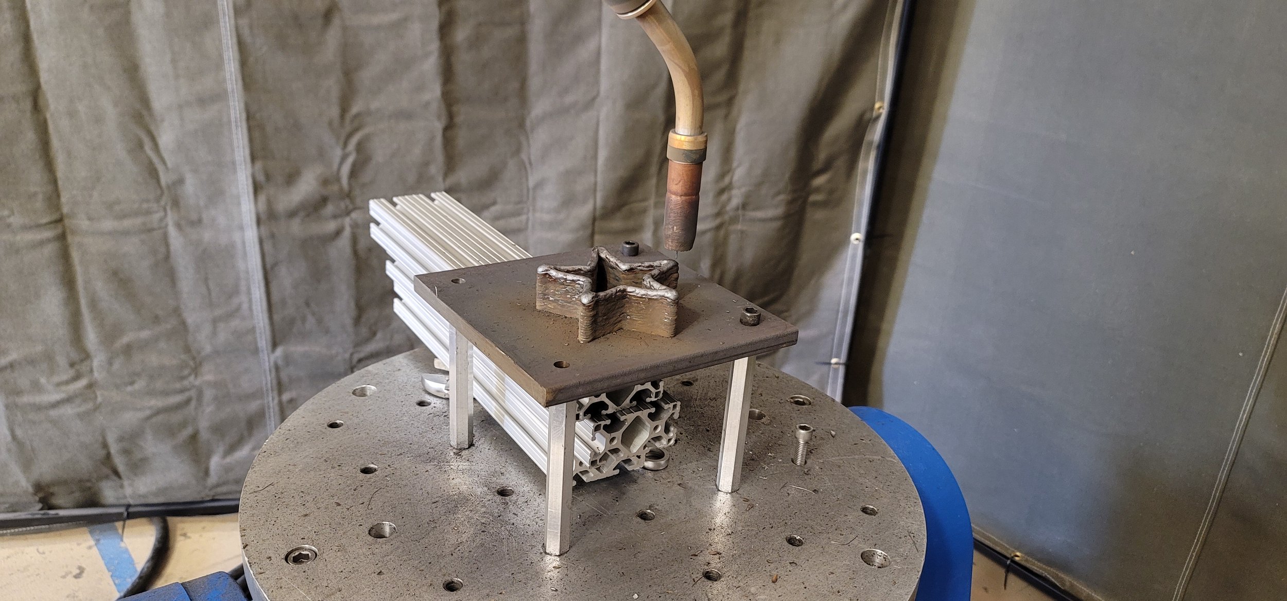
Motion was achieved by post-processing trajectories with a customized version of the robodk post-processor. Welding parameter files were defined on the robot's teach pendant like normal. A "User Frame" (reference system) was defined at the center of the metal plate to match the ROS environment. The robot's tool was edited to match the orientation used by ROS. This allowed us to generate robot programs without having to configure the ROS environment to match the workcell. Extra lines were added in the post-processor to start/stop welding. The program files were copied via ftp onto the controller and executed natively as Linear moves.
This hybrid ROS/robot controller set up allowed us to quickly set up this demonstration. The output of the tool is a list of cartesian poses. The post-processor converted these to linear moves in the robot's native format. The robot did the work of moving in lines at a set velocity; there was no reason to do additional planning or create joint trajectories. The robodk_postprocessors package available on Github has not been maintained or updated in some time. Numerous bugs exist and these needed work arounds.
Existing ROS drivers are focused entirely on joint trajectories. A different approach that would allow streaming of robot programs would be beneficial, and this is part of future work to be proposed.
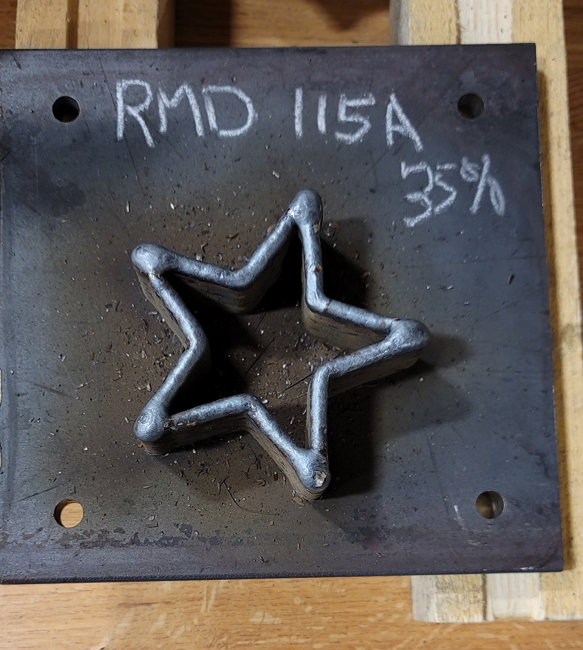
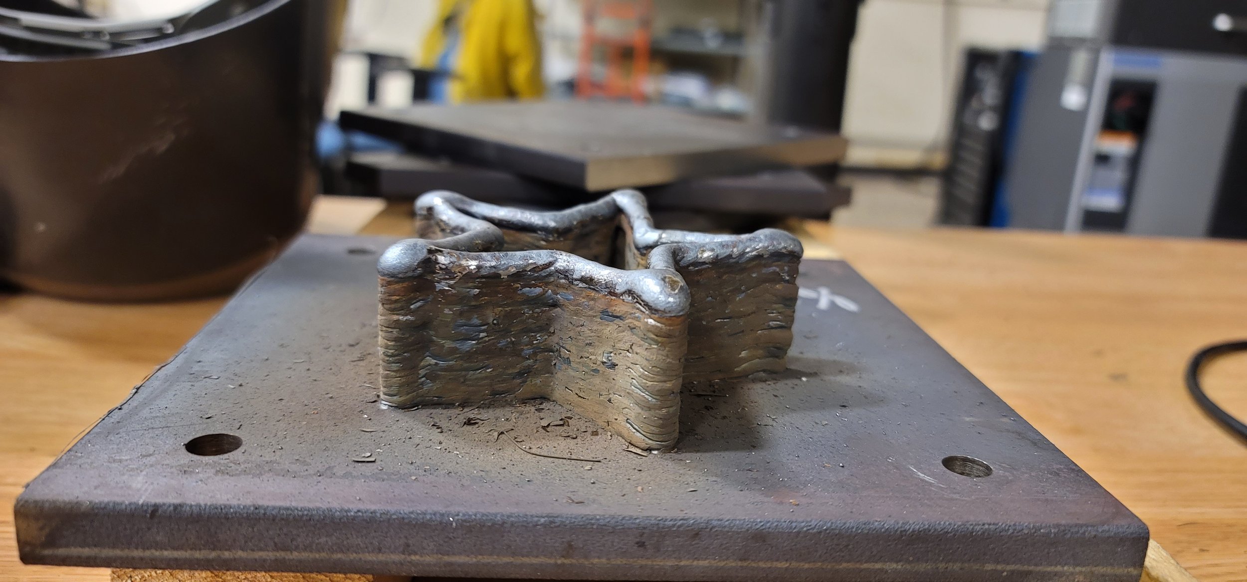
Below are two screenshots from the software for trajectories produced for a star and a rectangle with rounded corners. These shapes were included within the software as YAML files. The Contour generation algorithm was used with a 2.5 mm layer height and a 5.0 mm deposited material width for both shapes . The star shown below had three layers and the rounded rectangle had five layers. All other parameters were left to their default values.